Introduction
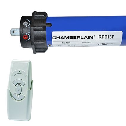
My shutters are operated with a Chamberlain RPD15F-05 tubular motor, using a 433MHz wireless remote to control the motion (up / down / stop). I wanted to be able to control the shutters with some simple Google Assistant voice commands without having to open my wooden encasement concealing the motor. I figured the best way to do this was to emulate the RF signals from the remote and ended up doing this with a Raspberry Pi and RF module.
A big thanks to George who wrote an awesome article on using the RF modules with the RPI on Instructables.
Note: If you do have access to the motor itself, you could just use a simple pre-made module like this to achieve the same thing.
Prerequisites
- Shutters / blinds with an RF controlled electric motor
- Remote that works on 433MHz RF band
- Raspberry PI with Raspbian installed and SSH / console access
- 433MHz RF transmit & receiver module
- Some jumper cables / breadboard to connect the module to the RPI
- Free IFTTT account
Installing software
Before hooking up any of the modules, we’ll install the necessary software on our Raspberry PI. Make sure Raspbian OS is installed on the RPI and go to the terminal (either through SSH or by hooking up a monitor). It is also a good idea to give your RPI a static IP as I explain in this post. Execute following commands.
sudo apt update
sudo apt install -y python3 python3-matplotlib
python3 -m pip install --upgrade pip
pip3 install RPi.GPIO
mkdir ~/shutters
We’ll also install Caddy to use as our webserver.
sudo apt install -y debian-keyring debian-archive-keyring apt-transport-https
curl -1sLf 'https://dl.cloudsmith.io/public/caddy/stable/gpg.key' | sudo tee /etc/apt/trusted.gpg.d/caddy-stable.asc
curl -1sLf 'https://dl.cloudsmith.io/public/caddy/stable/debian.deb.txt' | sudo tee /etc/apt/sources.list.d/caddy-stable.list
sudo apt update
sudo apt install caddy
Note: If you use SSH to connect to the RPI, you’ll need an X11 application to display graphs when decoding the signal. I use XQuartz on Mac; XMing works on Windows. Connect via SSH with the -X flag:
ssh -X pi@192.168.0.100Decoding 433MHz remote signal
As we’re going to emulate the remote control, step one is to learn the actual binary code and frequency timings the remote control is submitting to the receiver. For this part you’ll need to hook up the receiver module to the Raspberry PI.
Note: I currently do not know whether all Chamberlain shutter motors have the same code/delays. You could skip this step and try my codes in the transmit step to see if it works for you. Otherwise you’ll need to figure out the codes and delays yourself as described below.
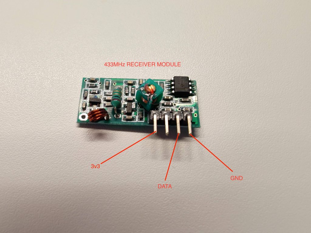
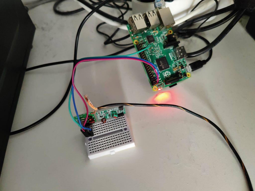
Connect the relevant pins of the receiver module to the pins on the Raspberry PI. You can connect them directly or use a breadboard like I did. I used a Raspberry PI 2 B for this project and my GPIO layout looks like this. If you use a different RPI version, you might want to look up the relevant GPIO scheme on Google.
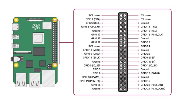
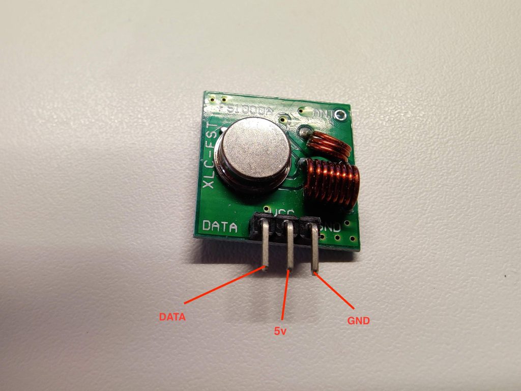
For the DATA pin, choose any GPIO numbered pin — I chose GPIO 13. The finished wiring will look something like this. Make sure to use a 3v3 power pin as using a 5V pin will break the board and possibly your RPI.
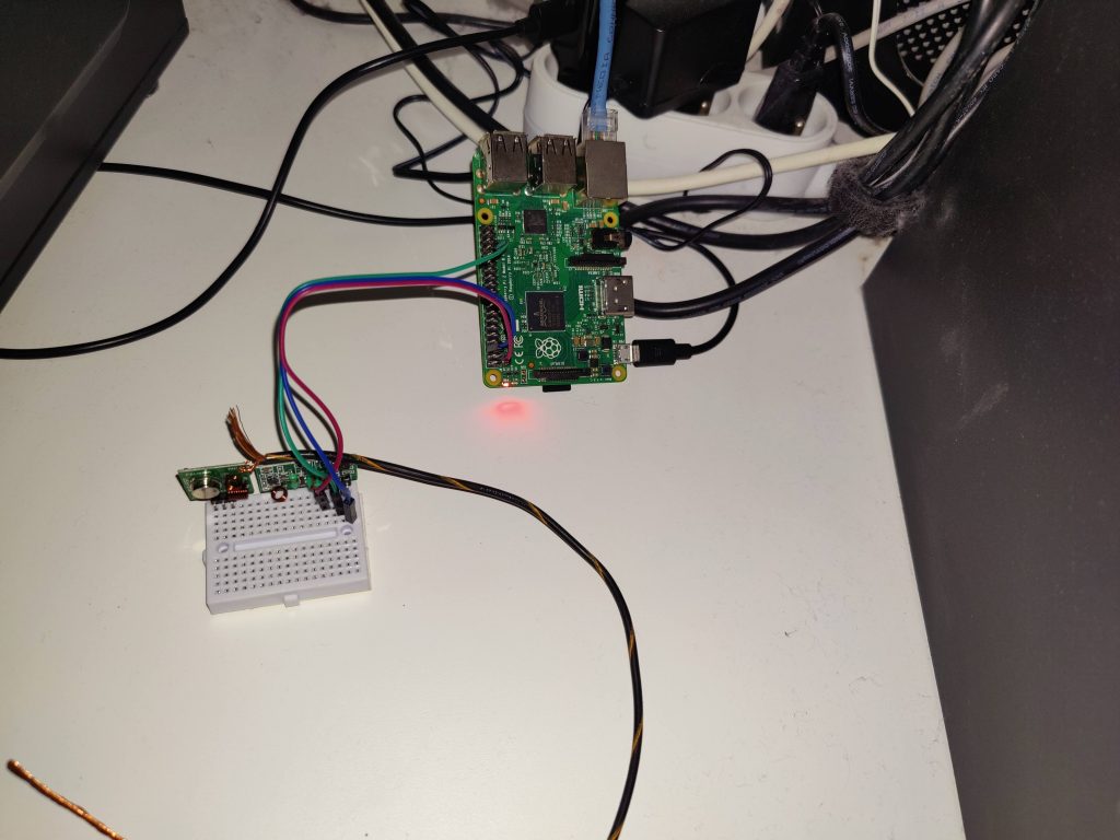
- Green = DATA
- Red = 3v3
- Blue = GND
With this now hooked up, power on your RPI and go to the shutters directory using a GUI-enabled shell as explained above.
cd ~/shutters
nano receive.py
Now paste the following code into the file. Adjust the RECEIVE_PIN value if you chose another GPIO pin.
# receive.py
from datetime import datetime
import matplotlib.pyplot as pyplot
import RPi.GPIO as GPIO

RECEIVED_SIGNAL = [[], []]  # [[time of reading], [signal reading]]
MAX_DURATION = 8
RECEIVE_PIN = 13

if __name__ == '__main__':
    GPIO.setmode(GPIO.BCM)
    GPIO.setup(RECEIVE_PIN, GPIO.IN)
    cumulative_time = 0
    beginning_time = datetime.now()
    print('**Started recording**')
    while cumulative_time < MAX_DURATION:
        time_delta = datetime.now() - beginning_time
        RECEIVED_SIGNAL[0].append(time_delta)
        RECEIVED_SIGNAL[1].append(GPIO.input(RECEIVE_PIN))
        cumulative_time = time_delta.seconds
    print('**Ended recording**')
    print(f'{len(RECEIVED_SIGNAL[0])} samples recorded')
    GPIO.cleanup()
    print('**Processing results**')
    for i in range(len(RECEIVED_SIGNAL[0])):
        RECEIVED_SIGNAL[0][i] = RECEIVED_SIGNAL[0][i].seconds + RECEIVED_SIGNAL[0][i].microseconds/1000000.0
    print('**Plotting results**')
    pyplot.plot(RECEIVED_SIGNAL[0], RECEIVED_SIGNAL[1])
    pyplot.axis([0, MAX_DURATION, -1, 2])
    pyplot.show()
Save the file with ctrl+x and then run the script. When you see Started recording, press one of the buttons on your remote for about a second.
python3 receive.py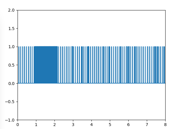
If everything went well, you’ll see a graph like this pop up. The dense part is what we’re looking for — it clearly is a signal sent over the 433MHz band. The other ups and downs are noise. Use the zoom tool and draw a rectangle over the dense part.
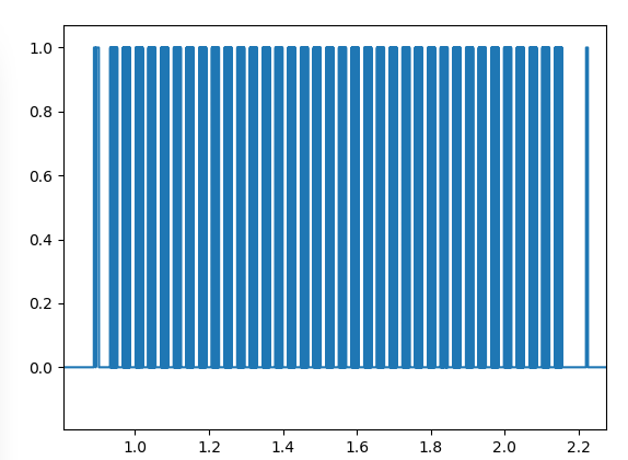
Here you clearly see a repeated signal. Zoom in even further and select one dense block.
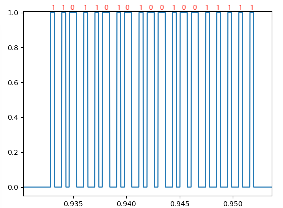
As you can see, we’ve now identified a single instance of the binary code. The short ups are 1s and the long ups are 0s. My up button produced 1101101010010011111. Repeat this step for all the buttons on your remote (up / stop / down).
up   = '1101101010010011111'
down = '1101101010010011000'
stop = '1101101010010011101'
These were my codes. I have no idea if these are the same for all Chamberlain shutter motors as I only have 1 in my home.
There is one step left in the decoding: finding out the timings between the long and short signals, as well as the timing between the repeated blocks. I did this by zooming in as far as I could and holding my cursor over the lines to see the exact times, then subtracting them.
short_delay    = 0.00035
long_delay     = 0.00070
extended_delay = 0.015212
These are the correct delays for my code. I suspect they are the same for all Chamberlain RF motors but I’m not certain. You might need to measure the delays yourself using the graph.
Transmitting 433MHz remote signal
Now that we’ve learned our binary codes and delays, we can reproduce the exact signal using our 433MHz transmitting module. You can now remove the receiving module and hook up the transmit module.
Note that this time, we need to wire it to a 5V power pin instead of 3v3. You can also add a copper wire to the antenna pinhole to increase range.
I chose GPIO pin 13 again for my data. SSH into your RPI (no X11 application needed this time) and create a transmit.py file using nano. Switch out your GPIO pin number, codes and delays.
# transmit.py
import time
import sys
import RPi.GPIO as GPIO

up   = '1101101010010011111'
down = '1101101010010011000'
stop = '1101101010010011101'

short_delay    = 0.00035
long_delay     = 0.00070
extended_delay = 0.015212

NUM_ATTEMPTS = 15
TRANSMIT_PIN = 13

def transmit_code(code):
    GPIO.setmode(GPIO.BCM)
    GPIO.setup(TRANSMIT_PIN, GPIO.OUT)
    for t in range(NUM_ATTEMPTS):
        for i in code:
            if i == '1':
                GPIO.output(TRANSMIT_PIN, 0)
                time.sleep(long_delay)
                GPIO.output(TRANSMIT_PIN, 1)
                time.sleep(short_delay)
            elif i == '0':
                GPIO.output(TRANSMIT_PIN, 0)
                time.sleep(short_delay)
                GPIO.output(TRANSMIT_PIN, 1)
                time.sleep(long_delay)
            else:
                continue
        GPIO.output(TRANSMIT_PIN, 0)
        time.sleep(extended_delay)
    GPIO.cleanup()

if __name__ == '__main__':
    for argument in sys.argv[1:]:
        exec('transmit_code(' + str(argument) + ')')
Execute the script using up, stop, or down as an argument. Your shutters should now respond.
python3 transmit.py downNote: I am following more or less what George did on Instructables. His 1s and 0s looked different than mine and I had to adjust the transmit script and switch the delays around. If you’re following this guide for something other than a Chamberlain shutter motor, you might need to switch some things around too, depending on your received graph.
Creating a simple web service
Awesome, we can now control the shutters using a Raspberry PI! The next thing we need is a way to trigger the script with Google Assistant. For this we’ll set up a very simple web service in Python using Flask so that we can call the script remotely (from IFTTT). SSH into your PI and execute the following commands.
cd ~/shutters
python3 -m venv venv
source venv/bin/activate
pip install flask gunicorn
nano webservice.py
Replace your codes in this file and set a strong password.
# webservice.py
from flask import Flask, request
from transmit import transmit_code

AUTH_STRING = "strong_password"

commands = dict(
    up   = '1101101010010011111',
    down = '1101101010010011000',
    stop = '1101101010010011101',
)

app = Flask(__name__)

@app.route("/webhook/<state>", methods=['GET'])
def run_webhook(state=None):
    auth = request.headers.get('X-Secret', None)
    code = commands.get(state, None)
    if auth and auth == AUTH_STRING and code:
        transmit_code(code)
        return "OK", 200
    return "Bad Request", 400
This creates a simple route on your RPI’s address. It returns 400 for a wrong/missing password or unknown command — basic security since this will be exposed to the internet.
flask run
curl http://127.0.0.1:5000/webhook/down --header "X-Secret: strong_password"
Flask run should only be used for development, so we’ll use Gunicorn behind a systemd service for production. Create a wsgi.py file in the same directory.
# wsgi.py
from webservice import app

if __name__ == "__main__":
    app.run()
sudo nano /etc/systemd/system/shutters.service# shutters.service
[Unit]
Description=Gunicorn workers to serve shutter web service
After=network.target
[Service]
User=pi
Group=www-data
WorkingDirectory=/home/pi/shutters
Environment="PATH=/home/pi/shutters/venv/bin"
ExecStart=/home/pi/shutters/venv/bin/gunicorn --workers 1 --bind 127.0.0.1:5000 -m 007 wsgi:app
[Install]
WantedBy=multi-user.targetUsing the pi user is not recommended — it is better to create a non-sudo user and add them to the www-data group. But let’s keep this guide as short as possible.
sudo systemctl start shutters
sudo systemctl enable shutters
sudo systemctl status shutters
The status command should show Gunicorn running and listening:
Jan 07 12:52:57 raspberrypi systemd[1]: Started Gunicorn instance to serve shutters.
Jan 07 12:52:58 raspberrypi gunicorn[961]: [2022-01-07 12:52:58 +0000] [961] [INFO] Starting gunicorn 20.1.0
Jan 07 12:52:58 raspberrypi gunicorn[961]: [2022-01-07 12:52:58 +0000] [961] [INFO] Listening at: http://127.0.0.1:5000 (961)
Jan 07 12:52:58 raspberrypi gunicorn[961]: [2022-01-07 12:52:58 +0000] [961] [INFO] Using worker: sync
Jan 07 12:52:58 raspberrypi gunicorn[961]: [2022-01-07 12:52:58 +0000] [963] [INFO] Booting worker with pid: 963
Setting up Caddy
I chose Caddy as it takes care of SSL and certificates automatically without needing certbot. This setup requires a static IP or a no-ip service linked to your RPI. I have an article describing how I set up DuckDNS and Caddy on my RPI — I recommend doing the same. Edit your Caddyfile at /etc/caddy/Caddyfile.
# /etc/caddy/Caddyfile
:80 {
    redir * https://{host}{uri} 301
}

your_domain.duckdns.org/webhook/* {
    reverse_proxy * 127.0.0.1:5000 {
        header_up X-Real-IP {remote}
        header_up X-Forwarded-Proto {scheme}
    }
}

:443 {
    respond * "Access denied" 403 {
        close
    }
}
Instead of the DuckDNS domain, you could also use your static IP directly or a real domain with a CNAME to your DuckDNS subdomain. This configuration handles HTTPS requests and redirects HTTP to HTTPS automatically.
caddy reloadThis reloads your Caddy configuration. You should now be able to call your web service from anywhere.
curl https://your_domain.duckdns.org/webhook/down --header "X-Secret: strong_password"Configuring IFTTT
Here comes the easy part. Go to https://ifttt.com, connect your Google account and Assistant. IFTTT currently allows 5 free applets — if you want more, you need a paid subscription. Alternatives like Zapier exist if needed.
Create a new Applet → IF step → Google Assistant → ‘say simple phrase’.
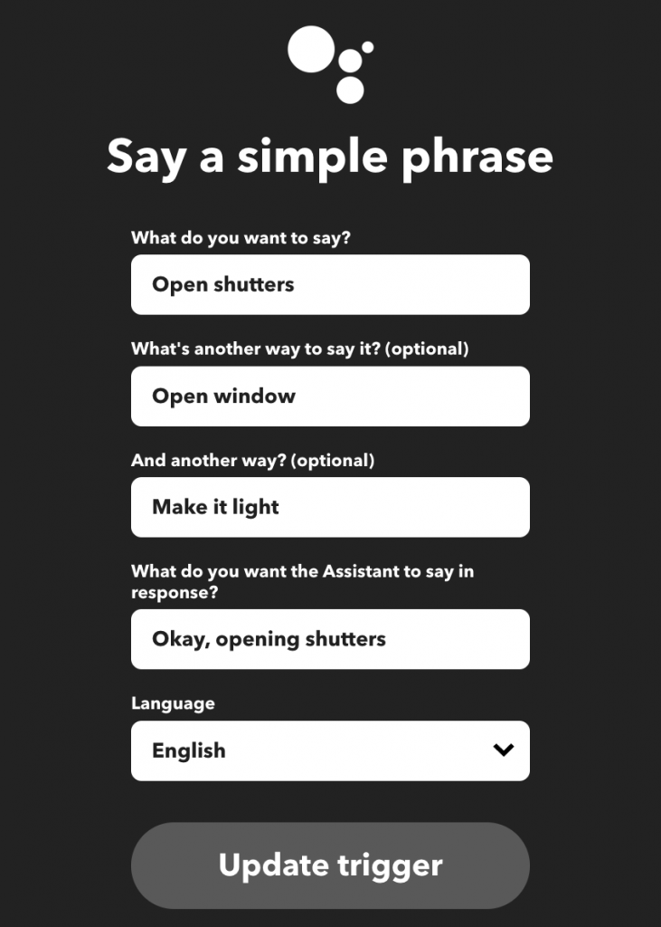
As the THEN step, select ‘Make a web request’ and configure it as follows.
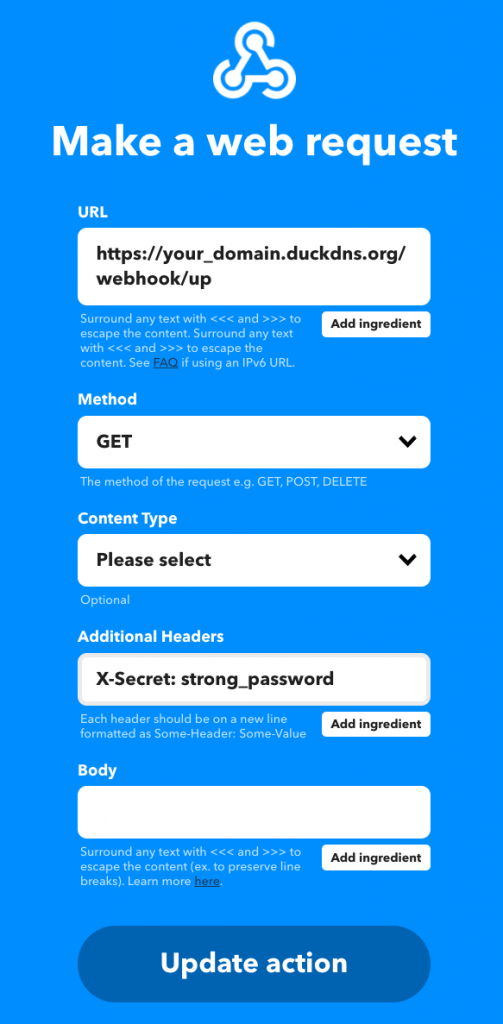
Save the applet and repeat for the close and stop actions. Your assistant will now call the web service on the RPI and transmit the RF signal to your shutters whenever you say one of the trigger phrases.
This is quite a bit of work to circumvent breaking open the shutter enclosure, but I think it was worth it. If I ever get another appliance that works with a 433MHz RF remote, I’d be able to control it with Google Assistant as well — which is pretty neat.